Connecting Tasmota to Home Assistant and other weird noname devices
What problem do we have?
One day, a very naughty person decided that wiring the whole house (including the electric stove) on a single 2.5mm² cable was a very good idea.
Fire safety regulations and automatic fuses didn't agree with this fact.
So turning on the boiler and the oven at the same time causes a complete power outage in a single apartment, which frustrates me a lot. And going to unplug the boiler every time when I want to cook something is definitely not the thing that I want to do.
And because of this we are going to make a smart home so that I can control the boiler at least from my smartphone.
Las Planchas
A quick search on Amazon gave me SONOFF Zigbee Bridge 3.0 Gateway Hub, ,Soporte de Protocolo Dual,WiFi, Compatible con Dispositivos Zigbee Pro, Alexa & Google, also known as SONOFF ZBBridge-P only for 35€.
A quick googling revealed that there's some kind of opensource firmware for it. “I should buy it”, I thought.
At the same time to the cart went ZigBee Enchufe Inteligente Alexa 16A, 3680W Smart Plug con Monitor de Energía, Enchufe Temporizador con Control Remoto, Control por Voz y Funciones de Temporización, apoyo Alexa & Google Home (4 pieces for 45€), which later turned out to be Tuya TS011F.
And also for the change was thrown in Garza Smart - Bombilla LED Zigbee Estándar A60, 11W (equivale a 75W de incandescencia), E27, Requiere Puente/Bridge, RGB + CCT, Intensidad regulable, Programable, Control por voz y app, Alexa/Google, which for some reason pretended to be Tuya TZ3210.
What exactly this TZ3210 means, I have not been able to establish. Various sources say that it is either a switch, a humidity and temperature sensor, or as I can guess an RGB lightbulb.
Curing the bridge from the cloud
Since it's mauvais to dump all smart home data to some obscure cloud, the first thing to do is to put a new firmware to the bridge.
I followed this very detailed instruction How to flash Tasmota on Sonoff ZB Bridge Pro.
The only thing that caused some confusion is the GPIO00 pin. It should be pulled up to GND during the startup to put this la plancha into UART mode.
I had some difficult time trying to understand what went wrong, so you can track the successfulness of this operation with elegant screen /dev/ttyACM0 115200 and then look at the startup logs.
I won't describe the complete flashing process, as it's perfectly described in the link above, but... Fig. 1. How to suddenly get a heart attack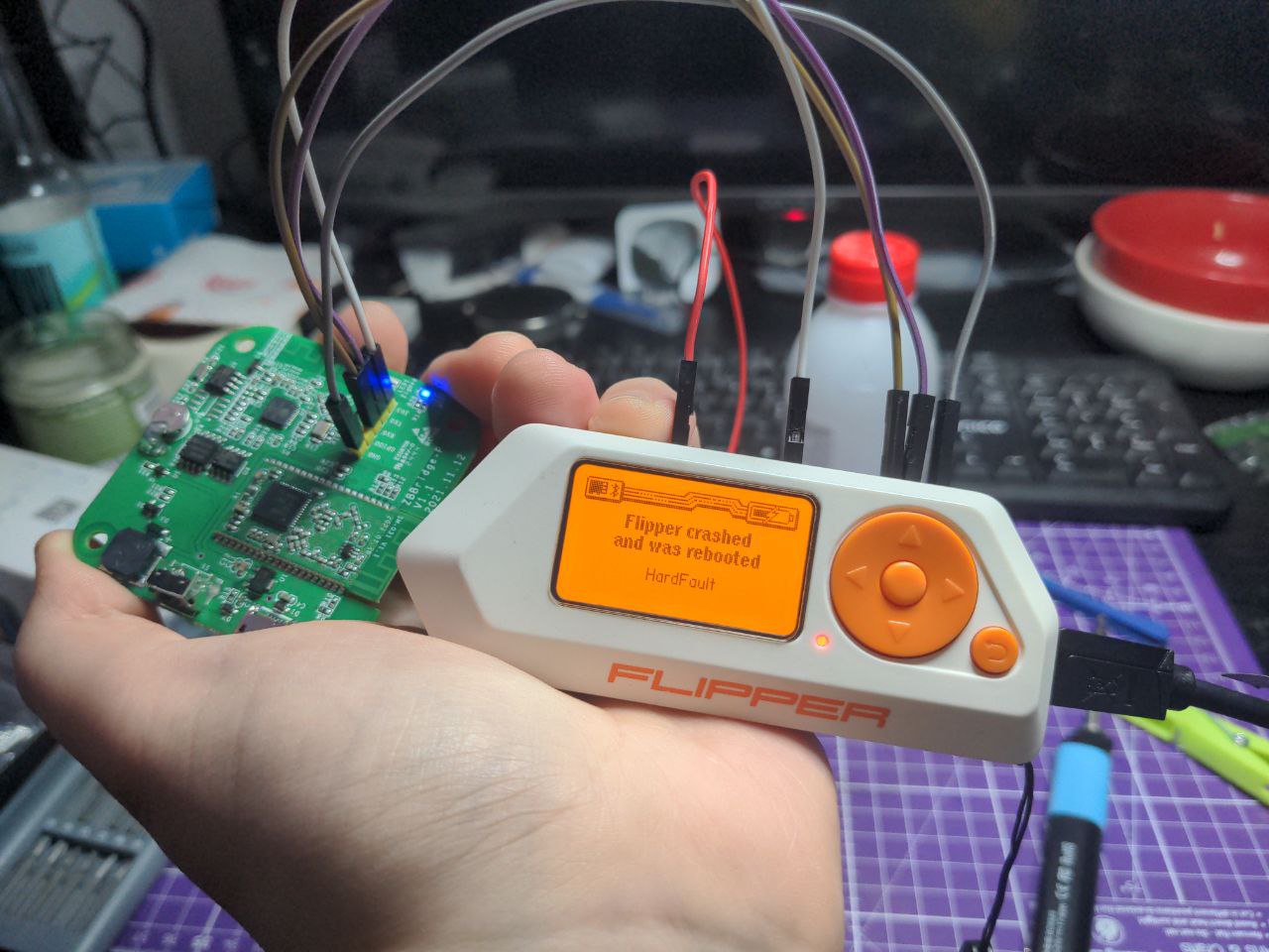
Fortunately, this bug was fixed a long time ago and someone just didn't update their Flipper's firmware for a long time.
Setting up secured MQTT
Despite the fact that ESP32 already has Wireguard implementation, Tasmota still doesn't support it, so I have to put MQTT server outside and configure SSL on it, so that random vanderers don't have fun with my sockets.
And with a slight nixos-rebuild switch ..., we will put Mosquitto on an external server with a static IP
users.users.mosquitto.extraGroups = [ "nginx" ];
services.mosquitto = {
  enable = true;
  listeners = [
    {
      address = "123.456.789.123";
      port = 1883;
      users = {
        tasmota = {
          acl = [
            "readwrite tasmota/#"
          ];
          password = "changeme";
        };
      };
      settings = {
        "allow_anonymous" = false;
        "require_certificate" = false;
        "cafile" = "/var/lib/acme/mqtt.example.com/fullchain.pem";
        "certfile" = "/var/lib/acme/mqtt.example.com/cert.pem";
        "keyfile" = "/var/lib/acme/mqtt.example.com/key.pem";
        "tls_version" = "tlsv1.2";
      };
    }
    {
      address = "10.20.0.1";
      port = 1883;
      users = {
        hass = {
          acl = [
            "readwrite #"
          ];
          password = "changeme";
        };
      };
    }
  ];
};
The mosquitto user was sent to the nginx group just to be able to use Let's Encrypt certificates.
I'm also using a system with two listeners. One is SSL protected, restricted to the core and looks outside, and the second one is in the internal VPN network, allowing to connect other clients, but about this later
Also worth noting are the lines “require_certificate” = false; and “tls_version” = “tlsv1.2.
First line disables TLS authorization, leaving the password one, and the second enables traffic encryption.
Without the first one Tasmota cannot connect to MQTT, and without the second one Mosquitto will ignore all configured certificates and will work in unencrypted mode.
On the Home Assistant side I have configured a bridge that will take all messages from the external MQTT and put them into the main MQTT.
Just because I already had MQTT configured for local stuff and didn't want to touch it.
services.mosquitto = {
  enable = true;
  listeners = [
    ...
  ];
  bridges = {
    "external2internal" = {
      addresses = [
        { address = "10.20.0.1"; port = 1883; }
      ];
      topics = [
        "tasmota/# in"
        "tasmota/cmnd/# out"
      ];
      settings = {
        remote_username = "hass";
        remote_password = "changeme";
      };
    };
  };
};
With this topics setup, I don't pull anything extra inside, and only direct commands for Tasmota can go outside.
But of course this can be skipped if there is only one MQTT.
AND DON'T FORGET TO OPEN THE PORT ON YOUR FIREWALL!
Connecting the bridge to the secured MQTT
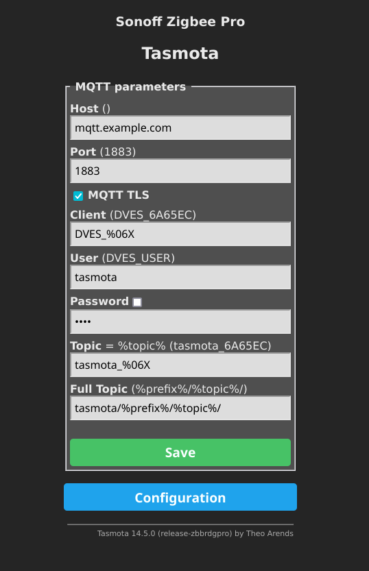
It's already obvious and self-explanatory here, except for a couple things.
Be sure to click the MQTT TLS checkbox so that it will be able to connect to our secure Mosquitto.
And in the Full Topic field you should add tasmota/ in the beginning, so that all messages are neatly piled into one group and we won't write each bridge address into ACL.
After pairing devices with the bridge (Just press the Zigbee Permit Join button and turn on las planchas), it is not unreasonable to check if everything is working properly and the messages from the devices are getting to MQTT.
Subscribe to tasmota/# and wait for something to be appeared there.
If nothing appeared for a long time, go back to the beginning and think about what can went wrong.
Repeat until you are completely satisfied.
Exploring the devices
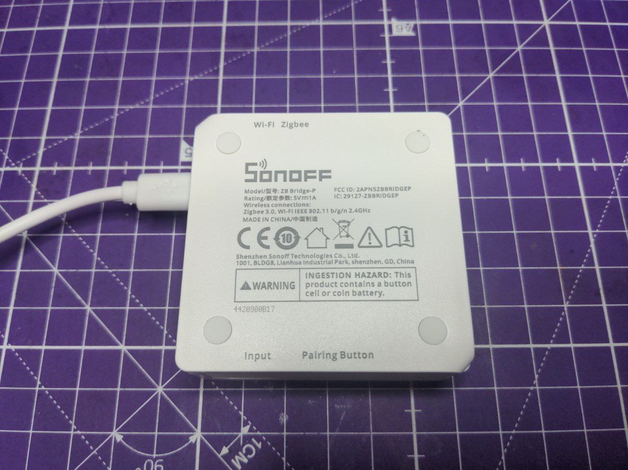
Fig. 2. SONOFF ZB Bridge-P
This is where the hell and Wisconsin begins.
The thing is that Tasmota can't do auto discovery. To be more precise, it can, but only for Tasmota running end devices and through their own plugin.
And since we have a bridge, two facts follow from this:
- We don't need a plugin, raw MQTT is more than enough.
- No one will help us.
But first we should arm ourselves with the console on the bridge itself and see what we have there. Fig. 3. Green and scary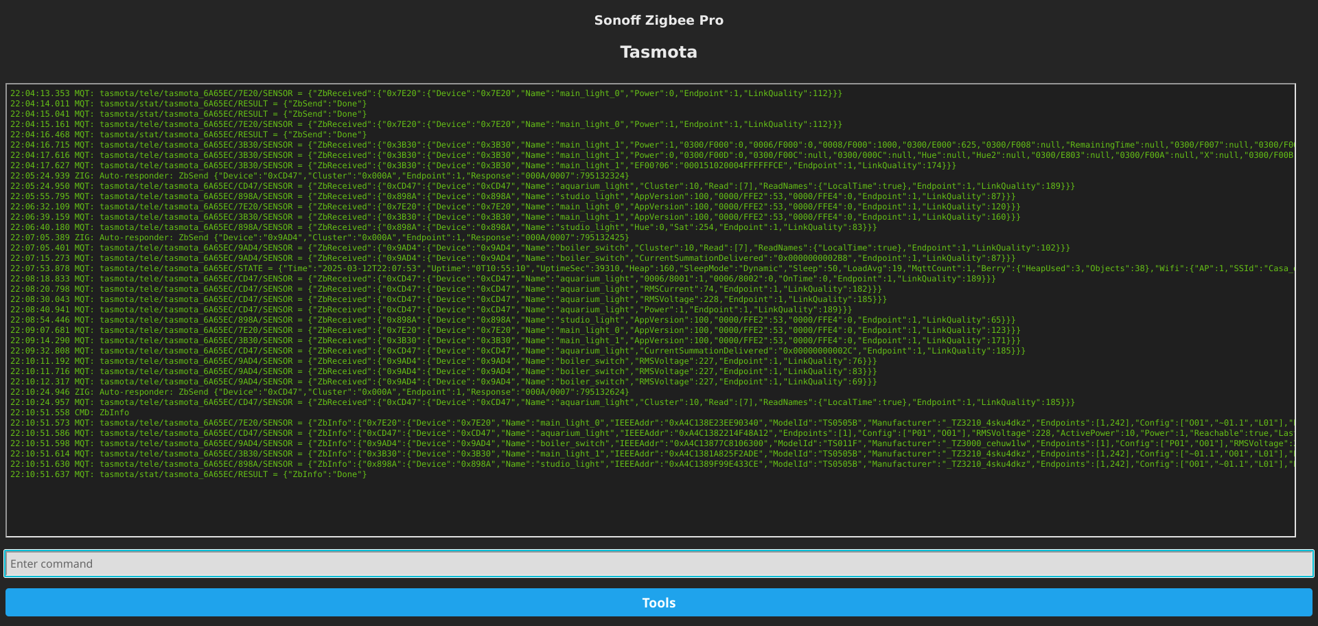
We go to Tools > Console in the bridge web interface and start poking everything around with a stick.
The full list of commands can be found here: Tasmota Commands, but now we are only interested in the Zigbee part.
To be more precise, the commands ZbInfo, ZbName and ZbSend.
ZbInfo
By typing ZbInfo into the terminal, you can get (mostly) all information about the connected devices.
The result is usually a mess like this
20:03:18.524 MQT: tasmota/tele/tasmota_6A65EC/7E20/SENSOR = {"ZbInfo":{"0x7E20":{"Device":"0x7E20","Name":"main_light_0","IEEEAddr":"0xA4C138E23EE90340","ModelId":"TS0505B","Manufacturer":"_TZ3210_4sku4dkz","Endpoints":[1,242],"Config":["O01","~01.1","L01"],"Power":1,"Dimmer":254,"Hue":0,"Sat":0,"X":24218,"Y":15601,"CT":499,"ColorMode":1,"RGB":"FFFFFF","RGBb":"FFFFFF","Reachable":true,"LastSeen":4,"LastSeenEpoch":1741806194,"LinkQuality":91}}}
20:03:18.536 MQT: tasmota/tele/tasmota_6A65EC/CD47/SENSOR = {"ZbInfo":{"0xCD47":{"Device":"0xCD47","Name":"aquarium_light","IEEEAddr":"0xA4C1382214F48A12","Endpoints":[1],"Config":["P01","O01"],"RMSVoltage":226,"ActivePower":10,"Power":1,"Reachable":true,"LastSeen":6,"LastSeenEpoch":1741806192,"LinkQuality":185}}}
20:03:18.548 MQT: tasmota/tele/tasmota_6A65EC/9AD4/SENSOR = {"ZbInfo":{"0x9AD4":{"Device":"0x9AD4","Name":"boiler_switch","IEEEAddr":"0xA4C13877C8106300","ModelId":"TS011F","Manufacturer":"_TZ3000_cehuw1lw","Endpoints":[1],"Config":["P01","O01"],"RMSVoltage":226,"ActivePower":0,"Power":0,"Reachable":true,"LastSeen":73,"LastSeenEpoch":1741806125,"LinkQuality":98}}}
20:03:18.563 MQT: tasmota/tele/tasmota_6A65EC/3B30/SENSOR = {"ZbInfo":{"0x3B30":{"Device":"0x3B30","Name":"main_light_1","IEEEAddr":"0xA4C1381A825F2ADE","ModelId":"TS0505B","Manufacturer":"_TZ3210_4sku4dkz","Endpoints":[1,242],"Config":["~01.1","O01","L01"],"Power":0,"Dimmer":254,"Hue":0,"Sat":254,"X":38449,"Y":21476,"CT":283,"ColorMode":2,"RGB":"FF0000","RGBb":"FF0000","Reachable":true,"LastSeen":136,"LastSeenEpoch":1741806062,"LinkQuality":163}}}
20:03:18.578 MQT: tasmota/tele/tasmota_6A65EC/898A/SENSOR = {"ZbInfo":{"0x898A":{"Device":"0x898A","Name":"studio_light","IEEEAddr":"0xA4C1389F99E433CE","ModelId":"TS0505B","Manufacturer":"_TZ3210_4sku4dkz","Endpoints":[1,242],"Config":["O01","~01.1","L01"],"Power":0,"Dimmer":42,"Hue":0,"Sat":254,"X":13578,"Y":14165,"CT":283,"ColorMode":2,"RGB":"FF0000","RGBb":"2A0000","Reachable":true,"LastSeen":150,"LastSeenEpoch":1741806048,"LinkQuality":65}}}
If you sit and read carefully, you can find:
Device- Short device address (0xAAAA). Usually used to refer to the device.ModelIdandManufacturer- The actual description of the model. If you look at the beginning of the article, you can see that cheap Chinese Tuya can be found under various pathos brands, but this is the place where the truth is revealed.Dimmer,Hue,Sat,X,Yand all other hardware-specific parameters that this device will send to MQTT.
The last ones will be especially useful for us, but we will talk about it later.
ZbName
Now it's about time to give all devices readable names so that we don't get confused later.
ZbName short_address,name will help us with this. The name, that we will give tp the device will pop up in every event and we can do something using it, but the main goal is just not to get confused with different addresses.
ZbSend
And now we can actively poke the device with the stick, because ZbSend allows us to send different messages and see how the device reacts.
We can, for example, put a stick in the smart socket.
ZbSend { “device”: “0x9AD4”, “send”: { “power”: “ON“ }} will turn the smart socket on, and ZbSend {”device": ‘0x9AD4’, ‘send’: { “Power”: “OFF” }} will turn it off, correspondingly.
How we know, that we need to send message { “Power”: “ON” }? It's the most interesting question.
And the answer to it would be "just guessed", but that's not actually true.
Let's take a closer look at the JSON from the output of the ZbInfo 0x9AD4 command
{
  "ZbInfo": {
    "0x9AD4": {
      "Device": "0x9AD4",
      "Name": "boiler_switch",
      "IEEEAddr": "0xA4C13877C8106300",
      "ModelId": "TS011F",
      "Manufacturer": "_TZ3000_cehuw1lw",
      "Endpoints": [
        1
      ],
      "Config": [
        "P01",
        "O01"
      ],
      "RMSVoltage": 226,
      "ActivePower": 0,
      "Power": 0,
      "Reachable": true,
      "LastSeen": 73,
      "LastSeenEpoch": 1741806125,
      "LinkQuality": 98
    }
  }
}
Among other things, here we can see the Power field with the value 0, i.e. “Off”.
And the trick with more readable ON and OFF I just found up in the Internets.
And if you look at the JSON from the lightbulb, there's more interesting stuff here.
{
  "ZbInfo": {
    "0x7E20": {
      "Device": "0x7E20",
      "Name": "main_light_0",
      "IEEEAddr": "0xA4C138E23EE90340",
      "ModelId": "TS0505B",
      "Manufacturer": "_TZ3210_4sku4dkz",
      "Endpoints": [
        1,
        242
      ],
      "Config": [
        "O01",
        "~01.1",
        "L01"
      ],
      "Power": 1,
      "Dimmer": 254,
      "Hue": 0,
      "Sat": 0,
      "X": 24218,
      "Y": 15601,
      "CT": 499,
      "ColorMode": 1,
      "RGB": "FFFFFF",
      "RGBb": "FFFFFF",
      "Reachable": true,
      "LastSeen": 4,
      "LastSeenEpoch": 1741806194,
      "LinkQuality": 91
    }
  }
}
In addition to Power we also have Dimmer, Hue, Sat, X, Y, CT, ColorMode, RGB and RGBb.
Spoiler: not all of these can be changed in the same way, but we have a general direction for digging for the API.
One more thing to mention (Backlog)
Ah, yes. There's one more thing to mention.
Even though we can do ZbSend { “device”: “0x7E20”, “send”: { “hue”: “128” }},
We can't do ZbSend { “device”: “0x7E20”, “send”: { “hue”: “128”, “sat”: “254” }} because we can change only one parameter per request.
As a quick workaround for the problem, you can use Backlog, the built-in language...
In short, you can just pass several commands in a row to this device, and then they will be executed sequentially.
And as a result, our command will look something like this:
Backlog ZbSend { “device”: “0x7E20”, “send”: { “Hue”: “128” }}; ZbSend { “device”: “0x7E20”, “send”: { “sat”: “254” }}
Good for quick hacks, but in practice it turns out that sending two commands is not the fastest process and instead you can sometimes find “undocumented” commands.
In case of this lightbulb there is a command Color which allows to set X and Y values at the same time, but about this again a little later.
Home Assistant
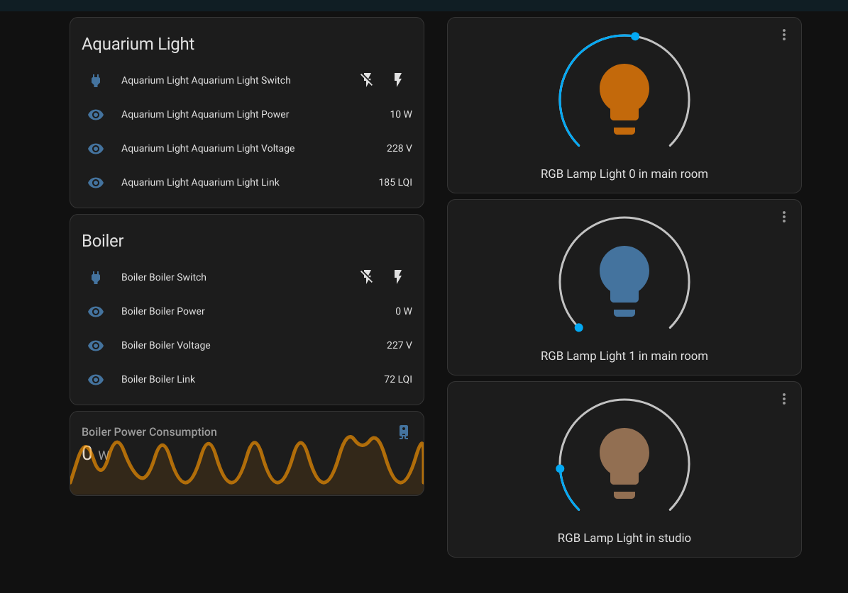
Fig. 4. Home Assistant
Remember when I said that Tasmota doesn't know how to do auto discovery? Well, here it is.
We're gonna write the configs.
By hands.
And may Nix and its ability to write functions for autogenerating YAML help us.
MQTT Topics
Essentially we only need two topics: tasmota/tele/tasmota_${gw_addr}/SENSOR to read telemetry and tasmota/cmnd/tasmota_${gw_addr}/ZbSend to send commands.
Perhaps a third tasmota/cmnd/tasmota_${gw_addr}/Backlog for executing Backlog commands.
Yes, any of the commands from the list can be called via MQTT by sending it to the appropriate topic, where the last part is the name of the command.
We will send JSON's and parse them too. So let's get to practice.
Switches and sensors
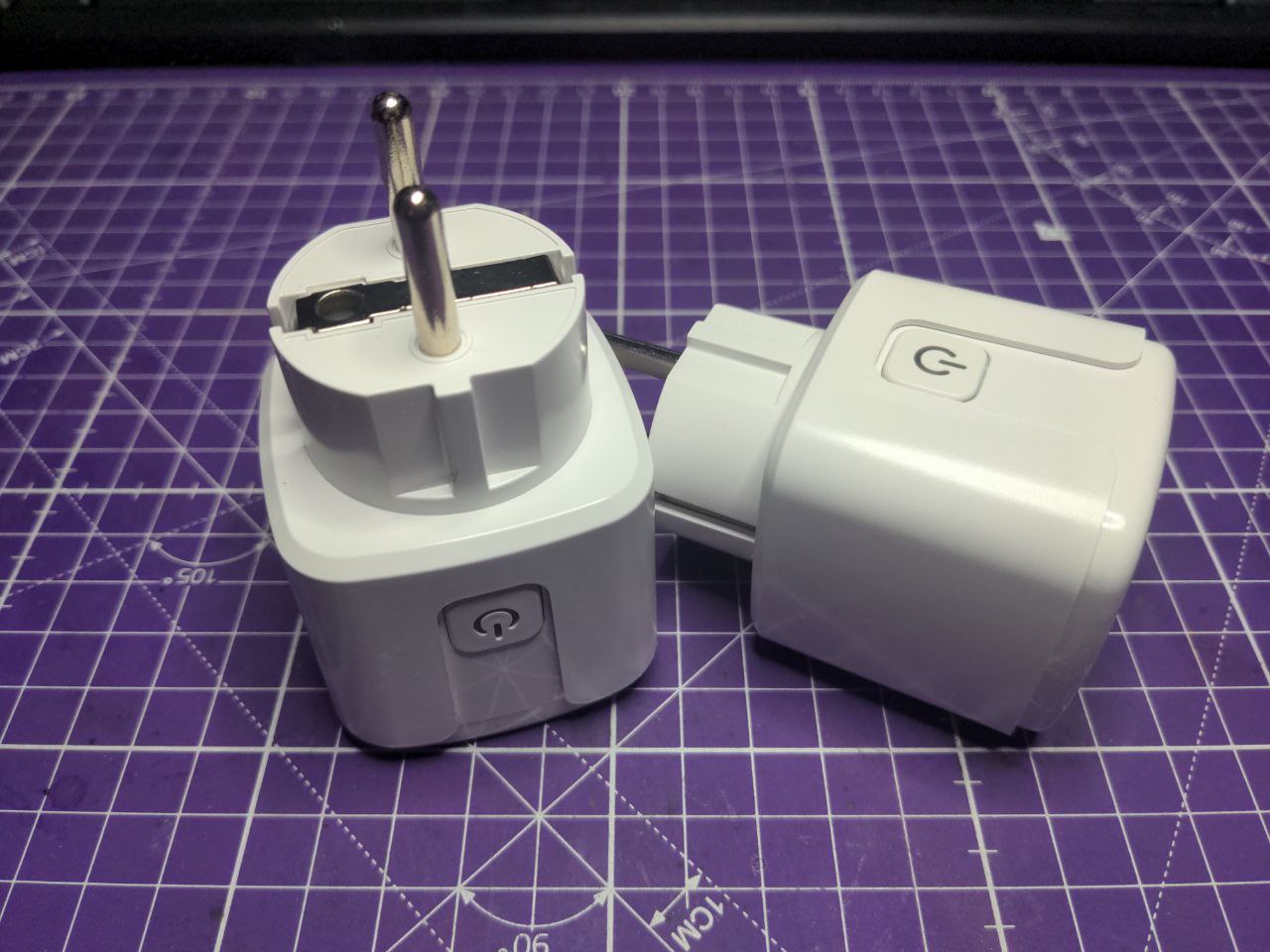
Fig. 5. Switches with sensors
Let's remember out JSON from the socket
{
  "ZbInfo": {
    "0x9AD4": {
      "Device": "0x9AD4",
      "Name": "boiler_switch",
      "IEEEAddr": "0xA4C13877C8106300",
      "ModelId": "TS011F",
      "Manufacturer": "_TZ3000_cehuw1lw",
      "Endpoints": [
        1
      ],
      "Config": [
        "P01",
        "O01"
      ],
      "RMSVoltage": 226,
      "ActivePower": 0,
      "Power": 0,
      "Reachable": true,
      "LastSeen": 73,
      "LastSeenEpoch": 1741806125,
      "LinkQuality": 98
    }
  }
}
In addition to Power, which controls turning the socket on and off, we also have RMSVoltage (measures the amount of volts) and ActivePower (measures the amount of ampers).
So let's go to writing the config:
mqtt = {
  switch = [
    {
      unique_id = "boiler_outlet_switch";
      name = "Boiler Outlet Switch";
      state_topic = "tasmota/tele/tasmota_6A65EC/SENSOR";
      value_template = "{{ value_json.ZbReceived['0x9AD4'].Power }}";
      command_topic = "tasmota/cmnd/tasmota_6A65EC/ZbSend";
      payload_on = ''{"device":"0x9AD4","send":{"Power": "ON"}}'';
      payload_off = ''{"device":"0x9AD4","send":{"Power": "OFF"}}'';
      retain = true;
      device_class = "outlet";
      device = {
        name = "Boiler Outlet";
        model = "TS011F";
        manufacturer = "Tuya";
        identifiers = [ "0x9AD4" ];
      };
    }
  ];
};
A full explanation of each parameter can be found in the corresponding documentation, so I'll run through the important stuff:
state_topic and command_topic are those topics for reading the state and sending commands. Usually right after receiving a command a device will throw a message with the changed state, which allows you not to rely on the “optimistic” strategy of Home Assistant and, albeit with a slight delay, but to know the actual state of the hardware.
value_template - a template for pulling a parameter value from JSON. Since JSON's are generated by the getway itself, you can copy the template from the example and only change the last part. Yes, I copied that from someone else too.
payload_on and payload_off - everything is clear here too, but later we will learn how to template them.
Of course, it will be unpleasant to write such a mess for each socket, so let's wrap everything in a function:
ts011f_switch = id: name: short_addr: gw_addr:
  {
    unique_id = id;
    name = "${name} Switch";
    state_topic = "tasmota/tele/tasmota_${gw_addr}/SENSOR";
    value_template = "{{ value_json.ZbReceived['${short_addr'].Power }}";
    command_topic = "tasmota/cmnd/tasmota_${gw_addr}/ZbSend";
    payload_on = ''{"device":"${short_addr}","send":{"Power": "ON"}}'';
    payload_off = ''{"device":"${short_addr}","send":{"Power": "OFF"}}'';
    retain = true;
    device_class = "outlet";
    device = {
      name = name;
      model = "TS011F";
      manufacturer = "Tuya";
      identifiers = [ short_addr ];
    };
  };
Wait, we also have sensors. So, we are writing functions for them too:
ts011f_sensors = id: name: short_addr: gw_addr:
  [
    {
      unique_id = "${id}_power";
      name = "${name} Power";
      state_topic = "tasmota/tele/tasmota_${gw_addr}/SENSOR";
      value_template = "{{ value_json.ZbReceived['${short_addr}'].ActivePower }}";
      unit_of_measurement = "W";
      device = {
        identifiers = [ "${short_addr}" ];
      };
    }
    {
      unique_id = "${id}_voltage";
      name = "${name} Voltage";
      state_topic = "tasmota/tele/tasmota_${gw_addr}/SENSOR";
      value_template = "{{ value_json.ZbReceived['${short_addr}'].RMSVoltage }}";
      unit_of_measurement = "V";
      device = {
        identifiers = [ "${short_addr}" ];
      };
    }
  ];
As a result, our config immediately starts to look nicer and we can add as many outlets as we have (and I have four of them):
mqtt = {
  switch = [
    (ts011f_switch "boiler_switch" "Boiler" "0x9AD4" "6A65EC")
  ];
  sensor = (ts011f_sensors "boiler" "Boiler" "0x9AD4" "6A65EC")
};
Lightbulbs
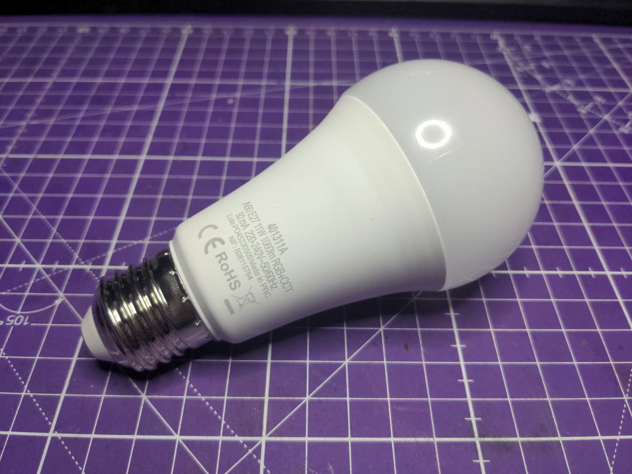
Fig. 6. Lightbulb
Now for the hard part. Lightbulbs.
Lightbulbs are completely cursed devices.
They look simple enough, but that simplicity is deceptive and lures the unfortunate people to the cliffs of insanity.
Cliffs of insanity
Let's take another look at JSON
{
  "ZbInfo": {
    "0x7E20": {
      "Device": "0x7E20",
      "Name": "main_light_0",
      "IEEEAddr": "0xA4C138E23EE90340",
      "ModelId": "TS0505B",
      "Manufacturer": "_TZ3210_4sku4dkz",
      "Endpoints": [
        1,
        242
      ],
      "Config": [
        "O01",
        "~01.1",
        "L01"
      ],
      "Power": 1,
      "Dimmer": 254,
      "Hue": 0,
      "Sat": 0,
      "X": 24218,
      "Y": 15601,
      "CT": 499,
      "ColorMode": 1,
      "RGB": "FFFFFF",
      "RGBb": "FFFFFF",
      "Reachable": true,
      "LastSeen": 4,
      "LastSeenEpoch": 1741806194,
      "LinkQuality": 91
    }
  }
}
This particular bulb can change power, temperature and color.
In fact, it doesn't do this simultaneously, but rather switches between modes, that we can see in ColorMode parameter.
However, we need this information only for research and debugging.
The first mode is a bright glow at full power with variable temperature. The parameters Dimmer and CT (Color Temperature) are responsible for this, correspondingly.
The second and third modes are RGB modes. They differ only in the way of color selection: Hue\Sat or X\Y.
It is logical to assume that we want to change the parameters Hue and Sat or X and Y, but here comes a question that is not the most obvious from the first time.
What exactly are the values that this parameters can take?
On the one hand, we can rely on common sense.
Hue is a circle, so the range of values should be 0...360.
And the XY coordinate system uses range 0.0 to 1.0.
But life is always more unpredictable than the theory.
And we are dealing with a lightbulb that is both a switch and a humidity sensor.
So the only adequate way to know the real range of values is to poke them with a stick and see what happens.
For example, Dimmer has a value range of 0...254. But when we try to set it to 255, the bulb returns null from the telemetry topic, which is very strange, because it is obviously an 8-bit variable.
My attempts to find the values of Hue and Sat did not lead to anything constructive, but X and Y simply refused to accept the command when I tried to put into them a value not in the range of 0..65279.
Why not 0..65535, as someone suggested on the Internets, thinking that this is a 16-bit variable?
Well, that's... Because! Just don't ask.
Compiling everything into Home Assistant
As a result, we have gathered all the knowledge, gained during the process of poking things with a stick, and now we are ready to write the function.
tz3210_lamp = id: name: short_addr: gw_addr:
  {
    unique_id = id;
    name = name;
    command_topic = "tasmota/cmnd/tasmota_${gw_addr}/ZbSend";
    payload_on = ''{"device": "${short_addr}", "send": {"Power": "ON"}}'';
    payload_off = ''{"device": "${short_addr}", "send": {"Power": "OFF"}}'';
    brightness_command_topic = "tasmota/cmnd/tasmota_${gw_addr}/ZbSend";
    brightness_command_template = ''{"device": "${short_addr}", "send": { "Dimmer": "{{ value - 1 }}" }}'';
    brightness_state_topic = "tasmota/tele/tasmota_${gw_addr}/SENSOR";
    brightness_value_template = "{{ value_json.ZbReceived['${short_addr}'].Dimmer }}";
    xy_command_topic = "tasmota/cmnd/tasmota_${gw_addr}/ZbSend";
    xy_command_template = ''{"Device": "${short_addr}", "send":{ "Color": "{{ x * 65279 }},{{ y * 65279 }}"}}'';
    xy_state_topic = "tasmota/tele/tasmota_${gw_addr}/SENSOR";
    xy_value_template = "{{ value_json.ZbReceived['${short_addr}'].X / 65279 }},{{ value_json.ZbReceived['${short_addr}'].Y / 65279 }}";
    color_temp_command_topic = "tasmota/cmnd/tasmota_${gw_addr}/ZbSend";
    color_temp_command_template = ''{"device": "${short_addr}", "send": { "CT": "{{ value - 1 }}" }}'';
    color_temp_state_topic = "tasmota/tele/tasmota_${gw_addr}/SENSOR";
    color_temp_value_template = "{{ value_json.ZbReceived['${short_addr}'].CT }}";
    device = {
      name = "RGB Lamp";
      model = "TZ3210";
      manufacturer = "Tuya";
        identifiers = [ short_addr ];
    };
  }
This function is just a beautiful collection of hacks to make the things somehow work.
Let's go in order
According to Home Assistant, Dimmer should take values 0...255, but as we already know, the maximum value there is 254, so just subtract one. Anyway you can't set a power in HA interface lower than 3%. Same thing for CT.
According to the same default Home Assistant settings, X and Y take values from 0 to 1.0, so the conversion back and forth is done simply by multiplication\division by the maximum possible value.
Besides, Color function is used here in xy_command_template, which allows to pass X and Y values in one command, which was accidentally found in the discussion about some other device I don't remember where.
If this function wasn't there, the config would look something like this:
xy_command_topic = "tasmota/cmnd/tasmota_${gw_addr}/Backlog";
xy_command_template = ''ZbSend {"Device": "${short_addr}", "send":{ "X": "{{ x * 65279 }}"}}; ZbSend {"Device": "${short_addr}", "send":{ "Y": "{{ y * 65279 }}"}}'';
This is the end
And on that note, my adventures are finally over.
The lights are lighting, the boiler is boiling and even the aquarium light has its own remote control.
I really didn't like the smart home, the process was just too stupid for production use.
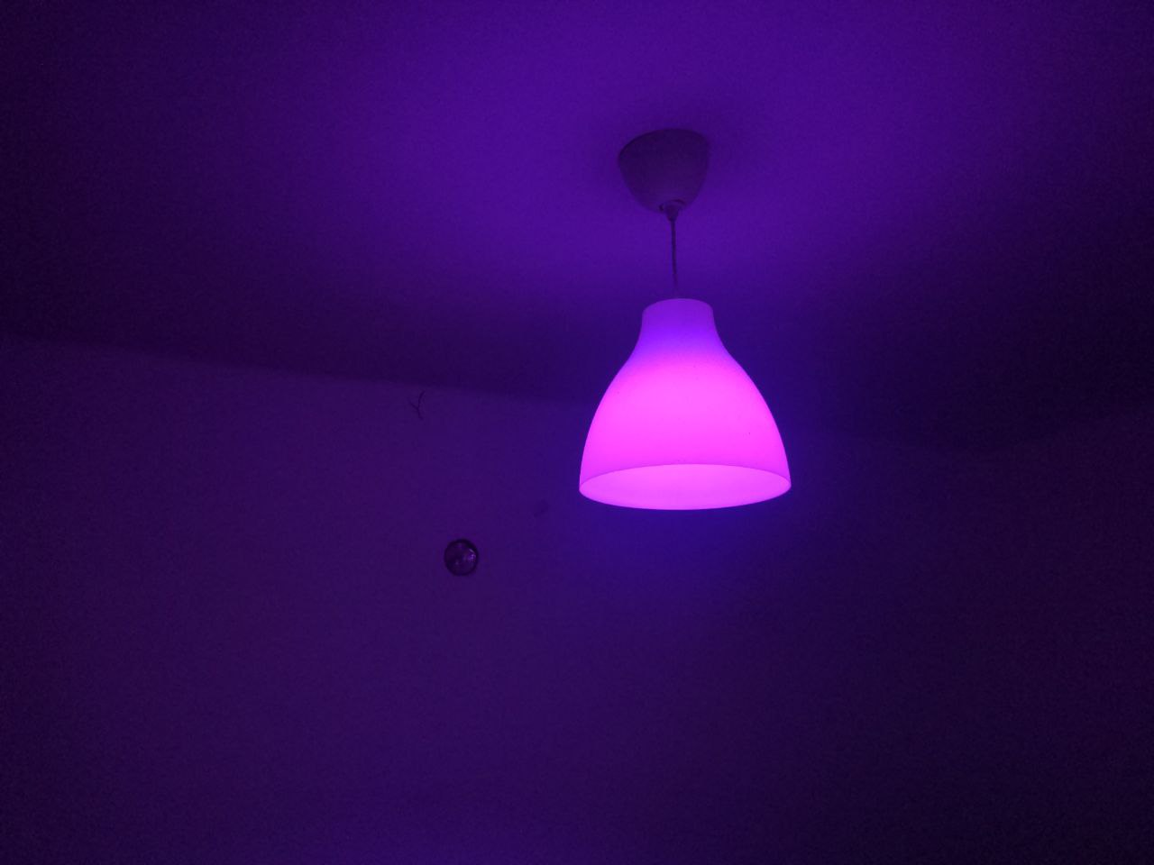
And the fucked up overpricings upset me even more. Fig. 7. Bisexual lighting
I'd better go to AliExpress to buy other hardware, at least there they can clearly write the model and manufacturer.